11.3 DESIGN OF SPACECRAF'T MAIN PROPULSION SYSTEMS
System Design
The reliability requirements for space missions have led to simple, stored inert gas pressure feed main propulsion systems (fig. 5-1), using conventional hypergolic Earth-storable propellants and redundant control components. For tube connections, the trend is to welded or brazed joints, with flexibility provided either by braided metal hoses or metal bellows. Integrated engine packages are preferred, consisting of thrust chamber and injector assembly, integrated propellant control valve package, and flight instrumentation. Besides meeting thrust and performance specifications, principal system design requirements for a spacecraft main engine are: (1) High reliability and crew safety (through redundancy in the control system; use of proven design concepts, materials, and fabrication techniques; and extended life and overstress testing) (2) High combustion stability rating with respect to perturbations during start and throttle transients (3) Capability of numerous starts, with repeatable cutoff impulse (4) Capability of deep throttling (optional, not required by all missions), with simple controls (5) Capability of propellant utilization and tank blowdown (ullage expansion) (6) One signal each, for start and cutoff (7) No purge, bleed, or lubrication equipment required (8) Effective isolation of the propellants from the system during long coast periods (use of propellant isolation valves) (9) System growth potential and flexibility to mission modifications (10) Sufficient protection against the effects of heat, nuclear radiation, and meteoric bombardment.
For missions involving intermittent propulsion system operation, during periods of more than a few months, the pressurization system design calls for special provisions, such as a completely sealed pressurant system. Pressuriza- tion could be provided by several individual pressurant tanks of different size, each of which remains sealed by explosive-actuated valves (fig. 7-72) until needed. A sealed pressurization system would not require gas venting during any part of the mission, thus eliminating losses due to intentional venting, or because of leakage past the vent valves.
In some applications, the propulsion system can be operated on a propellant tank ullage gas blowdown principle during the latter portion of the mission. This could reduce the required amount of pressurant (and pressurant tank volume) by as much as one-half of that for a regulated, constant pressure system.
Ignition of the main thrust chamber is critical with any multiple-start space propulsion system. If hypergolic propellants are used, ignition devices such as spark plugs of ASI units are not needed. However, hypergolics suffer from ignition delays at low temperatures (such as are encountered in space). Under the peculiar conditions of vacuum starting, irregular transients may occur upon ignition, such as violent chamber pressure surges. These may not be destructive, but they could place a severe burden on the control system.
For nonhypergolic propellants, spark plugs or augmented spark igniters (ASI) may be used. Spark plugs have the disadvantage of coronaarcing and electrical leakage, even in a partial vacuum. However, injection of unburned propellants into the thrust chamber or ASI with attendant vaporization usually builds up sufficient chamber back pressure to allow the plugs to function. In some systems, this process may be augmented by purge gases. Certain propellant combinations tend to ionize the gas around the plug and thus quench the spark.
Various schemes have been considered and developed for the deep throttling often required by spacecraft main propulsion systems. For instance, the Apollo LEM descent engine is required to vary thrust continuously over a range from 1050 to 10500 pounds to permit hovering. selection of a landing site, and the landing itself. Two alternate approaches to throttling are being pursued. One calls for variation of the thrust level by main propellant line throttle valves, combined with aeration of the propellants with helium gas, as shown in figure (b).
Such aeration requires a surprisingly small proportion of gas by weight. The alternative approach is to vary combustion chamber injection area, as shown in figure 4-47(a). Other potential space engine throttling methods include use of throttlable propellant gasifiers or precombustors, or the subdivision of the injector manifolds into segments, each of which can be shut off by simple on-off valves.
Figure 11-5 presents the schematic of a typical pressure-feed spacecraft main propulsion system using hypergolic Earth-storable propellants. A smaller and a larger pressurant tank satisfy pressurization requirements before and after a long coast period. The propellant tanks are equipped with positive expulsion diaphragms and remain pressurized to mission completion. An integrated main valve package contains main propellant throttling and isolation valves, including redundant features. This redundancy is obtained by series-parallel connection of the mechanically linked main propellant valves and increases system reliability, virtually eliminating critical failures (see also fig. 2-8). Aeration of
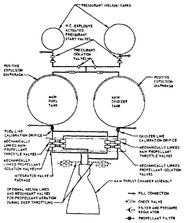 Figure 11-5.-Schematic of a typical pressurefeed spacecraft main propulsion system using hypergolic Earth-storable propellants.
propellants for deep throttling is provided by separate helium lines and redundant valves. If the system throttle requirements were removed, the main propellant throttling valves could be replaced by simple on-off types. Propellant filters are provided in both main propellant lines to minimize system line contamination with foreign particles.
The package design layout of the pressurefeed spacecraft main propulsion system schematically illustrated in figure 11-5 is shown in figure 11-6. The integrated main valve package is mounted directly to the main thrust chamber assembly, immediately upstream of the injector. The integrated engine assembly can be either rigidly mounted, or gimbal mounted, depending on requirements. Lightweight spherical propellant and pressurant tanks are secured by simple frames. An all-welded and brazed construction is employed for system assembly to prevent external leakage of pressurant gas or propellant.
In a complete space vehicle system, performance gains of the spacecraft stages will effect increasing weight savings for each succeeding lower booster stage, as indicated by equations (2-1) through (2-5). When planning future spacecraft missions, high-performance liquid propellants, such as and , thus definitely should be considered. For high mission total impulse requirements, these propellants, when used in turbopump-feed systems, tend to provide a considerable performance edge over pressure-feed systems (fig. 11-2). A turbopump-feed system for these applications must reliably supply high-pressure propellants to the combustion chamber, under vacuum and zero gravity conditions, and following extended coast
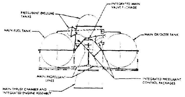 Figure 11-6.-Package design layout of a typical pressure-feed spacecraft main propulsion system using hypergolic Earth-storable propellants.
periods. All pumps must be fully primed prior to starting of the engine system to prevent delays in pump buildup and overspeeding. This may require ullage settling rockets, before and during main engine start, or positive propellant expulsion devices.
The well-proven turbopump subsystem designs and their operating concepts as established for large booster engine systems, and as discussed in preceding chapters, should be effectively applied to the design of turbopump-feed spacecraft main propulsion systems. In addition, the systems must be able to start an unlimited number of times (if possible from available tank pressure energy, without auxiliary starting devices) and to vary the thrust level (for some applications over a wide range). Major problem areas associated with turbopumps under space environmental conditions other than material considerations, are as follows: (1) Vacuum, temperature, and radiations effects on exposed high-speed bearings and dynamic seals (2) Micrometeorite penetration of fluid passages (3) Absence of the effects of gravitation on pump operation Figure 11-7 presents the package design layout of a hypothetical turbopump-feed spacecraft main engine system using a or
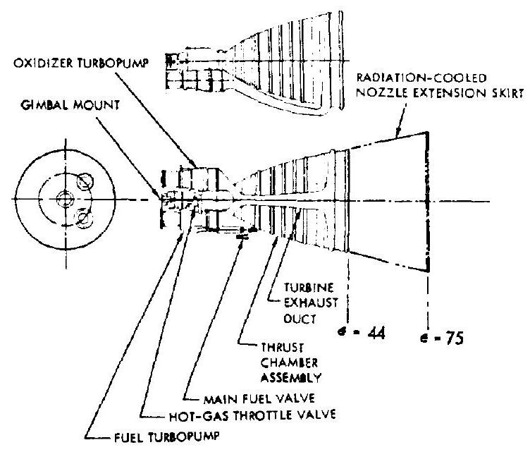 Figure 11-7.-Design layout of a hypothetical turbopump-feed spacecraft main engine system using a or propellant combination.
propellant combination. The main thrust chamber is regeneratively cooled by the fuel to a nominal nozzle expansion area ratio of 44:1. A radiation-cooled nozzle extension skirt may be added for certain missions to yield an overall expansion area ratio of . The propellants are supplied to the main chamber by two separate turbopump assemblies which are mounted to the thrust chamber body, resulting in an integral, compact engine. The turbines are driven by gases bled from the main combustion chamber in a parallel arrangement (fig. 6-13). A hot-gas throttle valve (such as shown in fig. 7-31) located upstream of the turbine inlets controls the turbine power, and thus the thrust level. A Y-type hot-gas duct is used to route the turbine exhausts into the main chamber nozzle. The entire engine package can be gimbaled at the gimbal mount by linear gimbal actuators.
Main Thrust Chamber Design
In addition to the design elements presented in chapter IV, primary requirements for thrust chambers of spacecraft main propulsion systems are: (1) Optimum steady-state cooling methods, with due consideration of application in space (2) Ability to withstand postrun soakback, intermittent operation, and storage in the space environment (3) Ability to enter planetary atmospheres at high velocities
Many of the thrust-chamber-cooling techniques described in chapter IV are applicable to space engines. Especially the ablatively cooled thrust chambers, which offer the inherent advantage of simplicity, ruggedness, and independence of propellant coolant flows (including their pressure drops), and thus offset their limited total life and relatively heavy weight, are suitable for most pressure-feed space engine systems using Earthstorable propellants at chamber pressures of less than 150 psia . In some applications, ablative cooling is supplemented by one or a combination of the following techniques: (1) Refractory throat inserts (2) Radiation-cooled nozzle extension skirts (3) Propellant film cooling
One of the problems associated with ablative cooling is the dimensional change of the chamber due to erosion. Nozzle throat erosion, if controlled and predictable, is acceptable for some engine systems and becomes proportionally less significant in larger thrust chamber units. For fixed-area injectors and fixed propellant supply pressures, propellant flow and engine thrust would increase with time, while specific impulse would decrease, due to throat enlargement. However, for a expansion nozzle operated in vacuum, the specific impulse loss would be only 0.5 percent, for as much as 10 percent increase in throat area, if the aerodynamic characteristics of the nozzle contour did not deteriorate.
One remedy against excessive throat erosion is the use of a refractory throat insert. A ceramic, silicon carbide, has been used extensively for throat inserts in space engine applications. It has a high melting point ( ), excellent thermal shock characteristics, relatively high thermal conductivity ( ), low coefficient of thermal expansion ( in/in- ), excellent oxidation resistance, and high abrasion resistance. Sometimes, a molybdenum backup sleeve is used when the silicon carbide insert cannot conduct heat sufficiently.
Another potential problem is the danger that the high-silica glass in the ablative material of the combustion chamber section becomes sufficiently fluid to be swept downstream and to be deposited in the throat section. This causes thrust variances and promotes an unsymmetrical velocity profile in this area. This phenomenon may be prevented by a liner of JTA ( 45 percent graphite, 45 percent zirconium diboride, and 10 percent silicon) inserted in the combustion zone. The liner is usually segmented, to provide a path for the gases from the pyrolyzed ablative (and reduce the across the liner), and to prevent cracks that would develop in an expanding unsegn ented liner.
Exclusively radiation-cooled thrust chambers would be subject to large stresses caused by the high temperatures in combustion zone and throat by the thrust transmission, and at the injector attachment points. By contrast, the radiationcooled nozzle skirt is designed to accept and emit only the heat flux transmitted by the expanding gases, and some of the loads imposed by thrust transmission. Molybdenum alloys. coated with molybdenum disilicide ( ) to prevent oxidation, are frequently used for nozzle skirt extensions (for skirts starting at to 12 ) which operate at sustained temperatures around . For nozzle skirts of higher expansion ratios (starting at to 45 ), Hastelloy-X is sometimes used at operating temperatures around . One potential disadvantage of radiation-cooled devices is their requirement to "see" space. A radiation-cooled skirt should face outboard and should not radiate undesirable heat to vehicle components. Radiation cooling appears unsuitable for clustered engines.
For exclusively ablative-cooled chambers used in or systems, analyses and tests have proven liquid hydrogen to be a very effective throat film coolant in low chamber pressure applications (less than 100 psia). As low as 0.1 percent of the total propellant flow used as the throat film coolant greatly reduces throat erosion for extended firing durations. The effect of such a small film coolant flow on system performance is so slight that it can be neglected. Ablative chambers with their throat film-cooled by liquid hydrogen, therefore, may be considered excellent prospects for future pressurefeed spacecraft main propulsion systems using or .
Following the firing of an ablative thrust chamber, the heat stored in the charred phenolic and silica reinforcement or in the throat insert refractory material soaks into the unburned virgin material. This postrun soakback propagates further thermal degradation, which might also be affected by the vacuum conditions, for 100 sec or more, until the mean temperature of the char is reduced to about . The weight of gas generated and expelled by soakback charring is about 15 percent of the weight of ablative material charred. It could cause a postrun residual impulse undesirably exceeding the desired minimum cutoff impulse. However, this effect is small for larger systems. For long-duration space missions, the temperature effects from solar radiation may cause vaporization of the ablative chamber material during coasting and should be prevented if possible.
Figure shows the design of a typical thrust chamber for a pressure-feed spacecraft main propulsion system using hypergolic
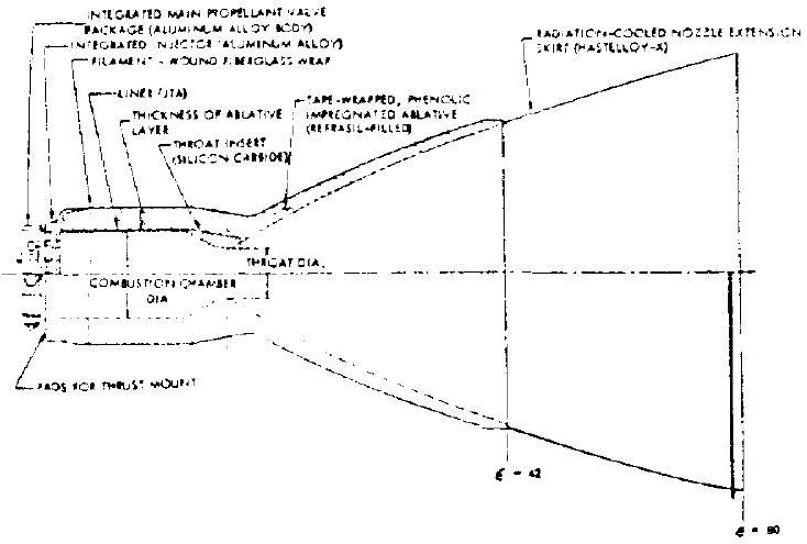 Figure 11-8.-Typical thrust chamber design details for a pressure-feed spacecraft main propulsion system using hypergolic Earth-storable propellants.
Earth-storable propellants at a chamber pressure of 125 psia. Refrasil-filled, phenolic-impregnated ablative materials are tape wrapped on a mandrel, at the combustion chamber and nozzle sections, up to an expansion ratio of 42 . A JTA liner and a silicon carbide insert are provided for combustion chamber section and throat, respectively. The chamber outer wall is made of fiber-glass filament, wound to accept hoop stresses, and then wrapped longitudinally (helically) to contend with meridional stresses. An insulating layer, consisting of the basic or another ablative material such as asbestos or alumina silica, is wrapped around the basic ablative layer and cured to reduce the rate of heat flux to the structural fiber-glass outer wall. A radiation-cooled skirt made of Hastelloy-X sheet is tape wrapped to the thrust chamber nozzle to provide the nozzle extension from an expansion ratio of to . An integrated injector is attached to the end of the combustion chamber and is made of an aluminumalloy forging. It is a conventional, fixed-orifice, single-ring, unlike-impinging doublet type.
Ablative thrust chambers for space engines, such as shown in figure 11-8, should be designed to permit many restarts. At the end of a specified total firing duration (design values: 2000 sec ), sufficient insulation material must remain between char and fiber-glass shell to limit the outer wall temperature to a specified maximum value (design values: ). Any heat soakback during offtimes between fir- ings should not affect total chamber duration. Equations (4-36) and (4-37) may be used to calculate the char depth. For Refrasil phenolic ablative thrust chambers operated at pressures around , and using and hydrazine type fuels, the following empirical equations may also be used to estimate char depth, including the effects of charring due to soakback: (1) For the combustion zone and the throat section (with or without liner and/or insert):
(2) For nozzle sections downstream of the throat:
where char depth, in thrust chamber cumulative firing duration, sec base of natural logarithms, 2.718 nozzle expansion area ratio at the section under consideration Once the char depth based on design duration, including effects of soakback, is determined, the thickness of the insulating layer required to keep the outer wall at the required temperature can be calculated.
For turbopump-feed space engine systems operated at relatively high chamber pressures, regeneratively cooled tubular-wall thrust chambers appear more suitable from heat transfer considerations. A possible disadvantage for space engine application is the response time from start signal to full thrust, which may be substantially increased if the propellant valve is located upstream of the coolant jacket. Relocating it to a point downstream of the jacket would reduce the response problem, but would introduce heat-transfer problems after shutdown, with the propellants trapped in the jacket.
Other potential problems are the heat-transfer characteristics during throttling. Also, tubular walls are more susceptible to meteoritic damage than are solid walls. In some applications, an optimum overall design may result from combining regenerative cooling with film cooling, and adding a radiation-cooled nozzle extension skirt.
Design of Control Components
The various aspects of control component design have been discussed in chapter VII. Pertinent considerations for the design of space main engine control components, in general and for propellant valves in particular, are: (1) Maximum reliability (2) Use of bellows for dynamic sealing in view of the need for long-term operating life in a vacuum environment (3) Combination hard and soft valve seats, for minimum leakage (4) Provision of a minimum of two seals and a vent between different propellants (5) Avoidance of sliding surfaces in components operating in a vacuum environment (6) Where possible, mechanical linkage of the propellant valve actuators by a mechanism that ensures positive, consistent, and synchronized opening and closing for smooth, repeatable ignition and thrust termination (7) Minimum electrical energy requirement for actuations
The basic design details for the various control components for space main engine systems, such as pilot valves, regulators, and vent valves, are quite similar to those for booster-stage applications. The mechanically linked, poppet-type dual-propellant valve arrangement shown in figure 11-9 is typical for main-propellant or propellant-isolation valves of space main engines using hypergolic Earth-storable propellants. In the valve shown, linked actuation is accomplished by locating the valve poppets in series, thus causing the oxidizer poppet motion to simultaneously move the fuel poppet. Complete separation of fuel and oxidizer is achieved by welded bellows seals located at both ends of the fuel poppet and at the connection end of the oxidizer poppet. Since valve actuation is provided by oxidizer fluid pressure, no bellows is required at the actuation chamber. The center vent chamber between valves sections is the critical area where propellant mixing must be prevented. However, both bellows would have to fail to cause this failure mode (reliability through redundancy). The design also incorporates allwelded static sealing joints, all-metal construction except for the Teflon dynamic poppet valve seals, and hermetically sealed solenoids or torque motors.
The valve is spring loaded normally closed, and additionally pressure unbalanced closed when inlet pressure is applied. Actuation to open is achieved by allowing the oxidizer fluid to enter the actuation chamber at nominal oxidizer valve inlet pressure which, in turn, overcomes the closing forces on the poppets. For on-off and isolation valve applications, the full open or closed valve positions are effected by a three-way solenoid pilot valve which, when energized, pressurizes the valve actuation chamber to open, and which, when deenergized, vents the same chamber allowing the pressure unbalance and the springs to close the poppets.
In the applications as a dual-propellant throttling valve, the position of the linked main poppets is controlled by a servo pilot spool valve which meters the control fluid flow (oxidizer) to the main valve actuation chamber. The pilot spool valve, in turn, is proportionally positioned by a servo torque motor, as a function of the command signal current and its polarity supplied from a servo amplifier. By means of properly shaped valve poppet contours, the main throttling valves control the flow of oxidizer and fuel to the main thrust chamber at constant mixture ratio, and thus regulate the main chamber pressure (thrust).
System Design of Propellant Storage for Space Missions
As previously mentioned, the storage of propellants for space-system propulsion represents an important design area. Cryogenic propellants require protection against high temperatures, particularly for extended storage periods. Earthstorable propellants, by contrast, require protection against low temperatures, because of the danger of propellant freezing. There are two basic design approaches to propellant storage for space missions, the vented and the nonvented systems. The selection of the optimum system design depends on mission, propellants type. and type of engine feed system.
In a vented storage system, propellant pressure and temperature are maintained at a constant value. This system is mainly used for cryogenic propellants. Any heat input to the propellants is absorbed by allowing a small percentage of boiloff. Since conditions will vary widely during travel, the net heat input to each propellant tank may be computed by a numerical integration process for the specific vehicle path, such as a complete orbit. This path can be divided into a number of intervals. Equilibrium skin temperatures and net heat fluxes (considering both internal and external sources) to the propellant tanks are then determined for each orbit location. By algebraically adding the net heat inputs for each, the net heat input rate for
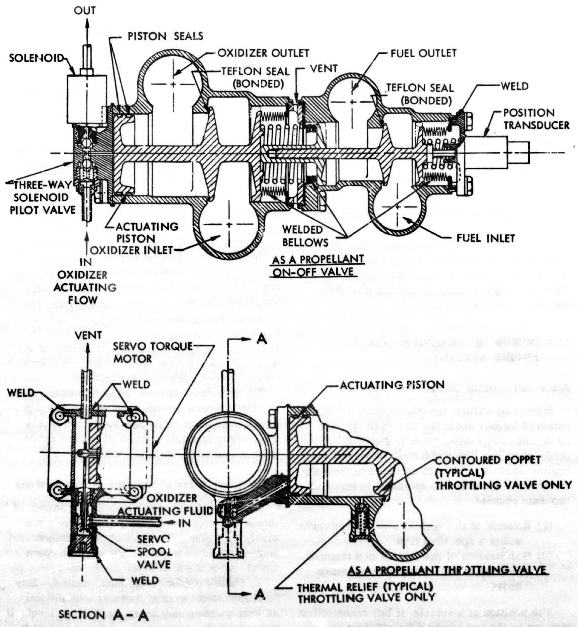 Figure 11-9.-Typical mechanically linked, poppet-type, dual-propellant on-off or throttling valve, for spacecraft main propulsion systems using hypergolic Earth-storable propellants.
one complete orbit can then be obtained and the amount of propellant boiloff per orbit calculated.
In a system without venting, any heat input to the propellant results in a propellant temperature rise and a corresponding increase in vapor pressure. This system can be applied to both cryogenic and Earth-storable propellants. The allowable pressure rise, and consequently the maximum heat input, is dictated by the allowable tank pressure. In this case, the storage analysis assumes an allowable vapor pressure rise during the mission, based on initial conditions. This permits determination of the final propellant temperature, expected changes in propellant density and ullage volume requirements, and pressure-dependent propellant tank weights. For cryogenics, it is usually assumed that the propellant experiences a uniform temperature rise. The maximum storage time is then computed by dividing the propellant heat capacity by the average rate of heat input. In this system, the storage weight penalties are composed of extra tank weight required to accommodate the pressure increase, the extra tankage required to allow for thermal expansion of the propellants, and the time-dependent insulation weight. For Earth storables, sufficient insulation is also required to prevent freezing.